What's new

Ask Programming ENE9028 RT809F

Question & Answer Forums

SureCanDo

Registered member
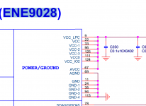
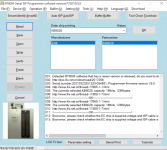
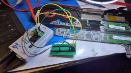
Hi all, I'm having trouble detecting a SuperIO. ENE KB9028 using RT809F which says it supports KB9028. it's programmable through SPI Flash. From schematics I have connected the RT809F as follows. Pin 1 CS to > Pin128, Pin 2 DO to > Pin120, Pin 4 G to Ground. Pin 5 DI to Pin119, Pin 6 CLK to Pin126, Pin 8 VCC to Pin9 of SuperIO. I also rotated Pin 2 and Pin 5 thinking I made mistake. It simply doesnt get detected. I checked VCC it gets 3.3 from Power supply when DC jack is plugged in.

I tried timing it like press read then Insert DC jack, or vice versa etc. No luck many times.
What am I doing wrong? thanks
I checked continuity and it's good for all cables from super IO to the RT809F
 

Download list
photoshot.jpg enepwrt.png rt809.png spi-flash.png
Hi ThienBui, you mean kso3= from super Io to rt809f pin 23 using rt809f port expander for example? I'm sorry it's my first time working on super Io.

Only 5 wires?
 
I know what you mean by
KSO3=23 KSI4=4 KSI7=1 KSI6=2 KSI5=3
KSO3 is going to Keyboard Pin 23.
KSI4 is going to Keyboard 4 etc.

But where is it going from Keyboard??? Which is which? Clk/DI/DO/VCC/CS etc.
 
Ok I think I found it
KSO3 GROUND
KSI4 CS/CE
KSI5 CLK
KSI6 DI
KSI7 DO
If this is correct, I still can't detect it :(

What do I do with VCC? I can see SuperIO Gets turned on due to 3V AW is present so I don't think I need to connect. Any advice?
 
Smdflea from Badcaps says:
kso3=4 (kbout3) , ksi4=13 (kbout12) , ksi7=16 (kbout15) , ksi6=15 (kbout14) , ksi5=14 (kbout13)


I don't know if it makes sense but thin Pin count is 28. Pin 23 from top and bottom, both are over 3V - how can that be for the ground?

SMDFlea recommendation of of KBOUT3 is 3.69V from one side and 3.3 from other side, if you count otherway. Just in case I got counting the wrong way, both are above 3V. What am I missing here?

Do I still need to connect 3.3V to Pin 8/VCC? I tried with and without, no difference. So confusing.
 
a mi me funciono ... pin 59 (kb9028) =pin5(rt80f) .... pin 60 kb9028=pin10 rt809f .... pin61 kb9028 = pin9 rt809f .... pin8 rt809f = gnd board ...... pin 62 kb9028 =pin6 rt809f ..... pin 42 kb9028 = gnd board conectar la board y leer usar cables cortos menos de 10 cm
 
Last edited:

Latest posts

Back
Top