What's new

BIOS ASUS ROG Strix G17 G713IC G513-6050A3249301-MB-A03(A3)

Star Rating
5.00 star(s)
G513-6050A3249301-MB-A03(A3)
G713IC AMD
G513IH g513-6050a3249301 IT8252E248A FGA00000.G513IH.211 OK

G513-6050A3249301 KB_pins=36 (CN250) LEFT DOWN 08MM PD0=29 PD1=20 PD2=15 PD3=23 PD4=14 PD5=16 PD6=12 PD7=30 BUSY=26 STB=18 AFD=28 INIT=21 SLIN=19 KSI4=22 KSI5=24 FLASH=248 CHIP=IT8252E-248A
boardview Asus ROG Strix G15 G513 - 6050A3249301-MB-A04(A4) Rev2.0 (60NR0500-MB2012).cad
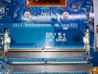


G513-6050A3249301-MB-A03(A3).jpg
 

Download list

G713IC.bin.zip
6 MB · Views: 992


EC.bin.zip
62.5 KB · Views: 270


Last edited:
Sir, can you fix this bios?
Every 40 seconds Windows immediately gets stuck, touchpad, keyboard, doesn't work at all... this is not the original BIOS. The original BIOS cannot be backed up because the BIOS IC is damaged
AMD BIOS no have repair
you can Programming any bios other
 
ASUS G513IH-HN086T
S/N- M8NRKD029042316
PROBLEM- NO POWER
I TRIED FORUM'S BIOS, ITS GETTING POWER ON BUT NO IMAGE
PLEASE BUILD THIS BIOSFOR ME
THANKS
 

Download list

x513eanook.rar
6.6 MB · Views: 1

G513-6050A3249301-MB-A03(A3)
G713IC AMD
G513IH g513-6050a3249301 IT8252E248A FGA00000.G513IH.211 OK

G513-6050A3249301 KB_pins=36 (CN250) LEFT DOWN 08MM PD0=29 PD1=20 PD2=15 PD3=23 PD4=14 PD5=16 PD6=12 PD7=30 BUSY=26 STB=18 AFD=28 INIT=21 SLIN=19 KSI4=22 KSI5=24 FLASH=248 CHIP=IT8252E-248A
boardview Asus ROG Strix G15 G513 - 6050A3249301-MB-A04(A4) Rev2.0 (60NR0500-MB2012).cad


View attachment 202224
please rebuild
 

Download list


Hi everyone,
Motherboard code: G513-MP-GBM 6050A3249305-MB-A01
IT8252E248A (keyboard controller) and IT5571E-128 were replaced due to malfunction. Currently, the computer powers on, but the keyboard and RGB lights are not working. I would like to load the EC ROM you provided, but I am unable to connect using the pin connections below.

G513-6050A3249301 KB_pins=36 (CN250) LEFT DOWN 08MM PD0=29 PD1=20 PD2=15 PD3=23 PD4=14 PD5=16 PD6=12 PD7=30 BUSY=26 STB=18 AFD=28 INIT=21 SLIN=19 KSI4=22 KSI5=24 FLASH=248

Could you please provide the correct pin connections? I have not been able to connect using Vertyanov and SVOD 4. I am using a 0.8mm 30-pin flex cable, and the keyboard connector is 36-pin.

Your help would be greatly appreciated!
 
Hi everyone,
Motherboard code: G513-MP-GBM 6050A3249305-MB-A01
IT8252E248A (keyboard controller) and IT5571E-128 were replaced due to malfunction. Currently, the computer powers on, but the keyboard and RGB lights are not working. I would like to load the EC ROM you provided, but I am unable to connect using the pin connections below.


Could you please provide the correct pin connections? I have not been able to connect using Vertyanov and SVOD 4. I am using a 0.8mm 30-pin flex cable, and the keyboard connector is 36-pin.

Your help would be greatly appreciated!
KB_pins=40 RIGHT DOWN 05MM PD0=1 PD1=2 PD2=3 PD3=7 PD4=9 PD5=10 PD6=13 PD7=16 BUSY=18 STB=4 AFD=5 INIT=6 SLIN=8 KSI4=11 KSI5=12 CHIP=IT5571E-128
 
KB_pins=40 RIGHT DOWN 05MM PD0=1 PD1=2 PD2=3 PD3=7 PD4=9 PD5=10 PD6=13 PD7=16 BUSY=18 STB=4 AFD=5 INIT=6 SLIN=8 KSI4=11 KSI5=12 CHIP=IT5571E-128
With the pin connection provided in the previous pages, I am now able to connect. However, I am now encountering a writing error. The Vertyanov error is as follows:

Check connection ...
Received ITE ID -> 8252 rev -> 03
INIT complete.
ERASE ...
There may be a problem with the block:
From ADR: 1E000h to 1E400h [FE (FCh)]
From ADR: 1E400h to 1E800h [FE (FCh)]
From ADR: 1E800h to 1EC00h [FE (FCh)]
From ADR: 1EC00h to 1F000h [FE (FCh)]
From ADR: 1F000h to 1F400h [FE (FCh)]
From ADR: 1F400h to 1F800h [FE (FCh)]
From ADR: 1F800h to 1FC00h [FE (FCh)]
From ADR: 1FC00h to 20000h [FE (FCh)]
ERASE complete.
The number of bytes value of FFh -> 83675
Writing, please wait ... complete.
Verify ...
ERROR (SRC-source DST-destination)
(first 256 bytes)
ADR 1E000h SRC=01h DST=46h
ADR 1E001h SRC=F0h DST=00h
ADR 1E002h SRC=12h DST=00h

In SVOD4, it also gives an error during the Blank Check phase.

By the way, to get the chip to read, I connected the battery without plugging in the DC power. While the programming flex cable was connected, I triggered the 5th pin on the keyboard flex. The PC powered on, and the programmer detected and identified the chip.
However, the writing error persists.
 
Back
Top