ACER SPIN 5 SP513-52N
CPU: Intel i7-8th Gen
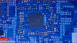
Motherboard: WOODY_KBL_R_MB 16924-3M 448.0CR10.003M
Features: Onboard RAM 8GB. Battery reset switch button on motherboard.
Problem: Powers on, no display. No keyboard activity i.e. Caps Lock/Numlock.
No physical damages.
Behaviour: Only motherboard with daughter board with power button. It pulls 0Amps at 19V. When power button pressed, 0.11A then 0, (BIOS Reset), then back on 0.11A, as fan spins reaches to 0.14A slowly and that's it. Power LED is on the daughter board.
A unique behavior is this: Battery and motherboard with daughter board with power button. It turns on immediately and pulls 1.86A depending on Battery level, it does charge the battery as I can see 12.381V increasing slowly 12.382 etc... There is a Battery Reset button switch on the motherboard, when it's on battery power, holding this button for 3 seconds does turn off the laptop and only way to turn back on is with power adapter inserted, this is normal behaviour.
Resistance readings when OFF in 200ohm range.
COILS
PWR_5V PL4502 O.L
PWR_3D3V PL4501 O.L
PWR_CHG_PH/BT+_R PL4401 O.L
PWR_VCCGT PL4801 9.3
PWR_VCORE/1V_CPU_CORE PL4702 5.74
PWR_VCORE/1V_CPU_CORE PL4701 5.75
PWR_VSSA/1V_VCCSA PL5001 19.34
PWR_1D0V PL5201 39
PWR_VDDQ PL5101 243
Voltage readings when ON WITH BATTERY:
COILS
PL4502 5.1
PL4501 3.3
PL4401 12.533 BATTERY
PL4801 0 - with OSCILLOSCOPE SET TO 500mV and 40.0us I can't capture anything with Trigger function on both sides of coil.
PL4702 0- with OSCILLOSCOPE SET TO 500mV and 40.0us I can't capture anything with Trigger function on both sides of coil.
PL4701 0- with OSCILLOSCOPE SET TO 500mV and 40.0us I can't capture anything with Trigger function on both sides of coil.
PL5001 1.04
PL5201 1
PL5101 1.204
BIOS CHIP PIN 1 AND 8 3.3V
PINS OF INTEREST:
KBC_PWRBTN_ 3.16V - DROPS TO 0 When power button pressed.
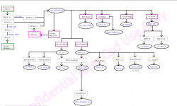
POWER SEQUENCE SIGNALS IN ORDER OF MEASURING VOLTAGE READINGS, skipped some signals to show the point of failure:
5V_S0 = 5.10V
3D3V_S0 = 3.0V
1D5V_S0 = 1.507
1V_VCCSA = 1.04
SYS_PWROK = 3.25 (THIS COMES FROM SUPER IO ENE KB9028Q PIN 106)
PLT_RST# = 0V
1V_CPU_CORE = 0V
ALL_SYS_PWRGD = 3.09
VCCST_PWRGD = 0.98
1V_CPU_CORE = 0V
CLK_CPU_BCLK CRYSTAL READING 24.39MHz AS PICTURED
VR_RDY = 3.29
PCH_PWROK = 3.29
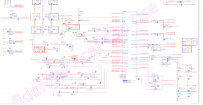
H_CPUPWRGD, RED IN SCHEMATICS. CAN'T FIND.
SYS_PWROK = 3.25
PLT_RST# = 0
VCC = 0
VCCGT = 0
4
CHIPS OF IMPORTANCE
RT3602AE AT PU4601*- It's responsible for enabling giving the 1V_CPU_CORE
Things I have tried in their order:
1. BIOS flash
2. Try different BIOS chip.
3. Reflow onboard RAM, just to a point of chip moving, then next RAM.
4. Flash EC.
I have uploaded the following for you:
1. Original BIOS bin as well as flashed BIOS bin.
2. Original EC bin and flashed EC bin.
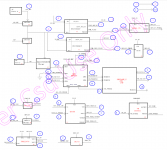
3. Schematics & Boardview
4. Images of interest.
CPU: Intel i7-8th Gen
Motherboard: WOODY_KBL_R_MB 16924-3M 448.0CR10.003M
Features: Onboard RAM 8GB. Battery reset switch button on motherboard.
Problem: Powers on, no display. No keyboard activity i.e. Caps Lock/Numlock.
No physical damages.
Behaviour: Only motherboard with daughter board with power button. It pulls 0Amps at 19V. When power button pressed, 0.11A then 0, (BIOS Reset), then back on 0.11A, as fan spins reaches to 0.14A slowly and that's it. Power LED is on the daughter board.
A unique behavior is this: Battery and motherboard with daughter board with power button. It turns on immediately and pulls 1.86A depending on Battery level, it does charge the battery as I can see 12.381V increasing slowly 12.382 etc... There is a Battery Reset button switch on the motherboard, when it's on battery power, holding this button for 3 seconds does turn off the laptop and only way to turn back on is with power adapter inserted, this is normal behaviour.
Resistance readings when OFF in 200ohm range.
COILS
PWR_5V PL4502 O.L
PWR_3D3V PL4501 O.L
PWR_CHG_PH/BT+_R PL4401 O.L
PWR_VCCGT PL4801 9.3
PWR_VCORE/1V_CPU_CORE PL4702 5.74
PWR_VCORE/1V_CPU_CORE PL4701 5.75
PWR_VSSA/1V_VCCSA PL5001 19.34
PWR_1D0V PL5201 39
PWR_VDDQ PL5101 243
Voltage readings when ON WITH BATTERY:
COILS
PL4502 5.1
PL4501 3.3
PL4401 12.533 BATTERY
PL4801 0 - with OSCILLOSCOPE SET TO 500mV and 40.0us I can't capture anything with Trigger function on both sides of coil.
PL4702 0- with OSCILLOSCOPE SET TO 500mV and 40.0us I can't capture anything with Trigger function on both sides of coil.
PL4701 0- with OSCILLOSCOPE SET TO 500mV and 40.0us I can't capture anything with Trigger function on both sides of coil.
PL5001 1.04
PL5201 1
PL5101 1.204
BIOS CHIP PIN 1 AND 8 3.3V
PINS OF INTEREST:
KBC_PWRBTN_ 3.16V - DROPS TO 0 When power button pressed.
POWER SEQUENCE SIGNALS IN ORDER OF MEASURING VOLTAGE READINGS, skipped some signals to show the point of failure:
5V_S0 = 5.10V
3D3V_S0 = 3.0V
1D5V_S0 = 1.507
1V_VCCSA = 1.04
SYS_PWROK = 3.25 (THIS COMES FROM SUPER IO ENE KB9028Q PIN 106)
PLT_RST# = 0V
1V_CPU_CORE = 0V
ALL_SYS_PWRGD = 3.09
VCCST_PWRGD = 0.98
1V_CPU_CORE = 0V
CLK_CPU_BCLK CRYSTAL READING 24.39MHz AS PICTURED
VR_RDY = 3.29
PCH_PWROK = 3.29
H_CPUPWRGD, RED IN SCHEMATICS. CAN'T FIND.
SYS_PWROK = 3.25
PLT_RST# = 0
VCC = 0
VCCGT = 0
4
CHIPS OF IMPORTANCE
RT3602AE AT PU4601*- It's responsible for enabling giving the 1V_CPU_CORE
Things I have tried in their order:
1. BIOS flash
2. Try different BIOS chip.
3. Reflow onboard RAM, just to a point of chip moving, then next RAM.
4. Flash EC.
I have uploaded the following for you:
1. Original BIOS bin as well as flashed BIOS bin.
2. Original EC bin and flashed EC bin.
3. Schematics & Boardview
4. Images of interest.
Download list
Schematics and BV.zip
3 MB · Views: 41
3 MB · Views: 41
BIOS.zip
9.3 MB · Views: 40
9.3 MB · Views: 40
SuperIO.zip
115.4 KB · Views: 22
115.4 KB · Views: 22
