What's new

Asus ASUS ROG G751JM

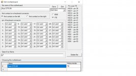
KB_pins=30 PD0=29 PD1=20 PD2=15 PD3=23 PD4=14 PD5=16 PD6=12 PD7=30 BUSY=26 STB=18 AFD=28 INIT=21 SLIN=19 KSI4=22 KSI5=24
I have an SVOD3 programmer, how should I translate it into its pinout?
KB_pins=30
PD0=29
PD1=20
PD2=15
PD3=23
PD4=14
PD5=16
PD6=12
PD7=30
BUSY=26
STB=18
AFD=28
INIT=21
SLIN=19
KSI4=22
KSI5=24
G751JM.jpg
 
KB_pins=30 PD0=29 PD1=20 PD2=15 PD3=23 PD4=14 PD5=16 PD6=12 PD7=30 BUSY=26 STB=18 AFD=28 INIT=21 SLIN=19 KSI4=22 KSI5=24

I think it auto comfig
There is no such auto-configuration function in the programmer.
The EC circuit is not new, I know it could program itself, but the circuit is original. Has corrupted KBC batch when updating BIOS via Windows.
It's hard for me to decode this pinout and connect to SVOD3 because there are other markings. I can easily do it with boardview, but there is a problem with SVOD3 having 32-pin keyboard support and the board has a 34-pin port.
Do you have any idea?
Pinout made for G751JM is posted on SVOD.
Works correctly.
 
Back
Top